What is a Frequency Response Analyzer?
A Frequency Response Analyzer (FRA) is a high precision measurement instrument used to analyze components, circuits and systems (known as devices under test, or DUT’s) in the frequency domain. An FRA typically generates a sinusoidal signal and injects it into a component, circuit or system under test. This signal is measured at the point of injection using one of the input channels on the FRA, usually channel 1.
The injection signal travels through the device under test and the same signal is measured simultaneously by the frequency response analyzer at a second reference point – normally the output of the system, using channel 2. The use of sinewaves allows the frequency domain behavior (the frequency response) of a system to be determined.
Frequency Response Analyzer connection to DUT
Frequency Response Analyzer connection to DUT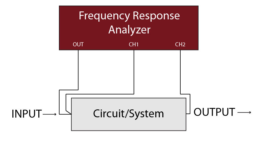
The diagram on the left illustrates a basic overview for connecting an FRA to a DUT, the signal generator and reference channel (CH1) are connected to the input of the DUT, CH2 is connected to the output of the DUT.
This connection method enables the frequency domain behavior (also known as the frequency response) of the DUT to be determined. The response of the DUT over a specific frequency range can be determined by performing a “sweep”, this involves stepping the injected frequency across a range of frequencies pre-selected by the user.
Frequency Response Analyzer block diagram
Frequency Response Analyzer block diagram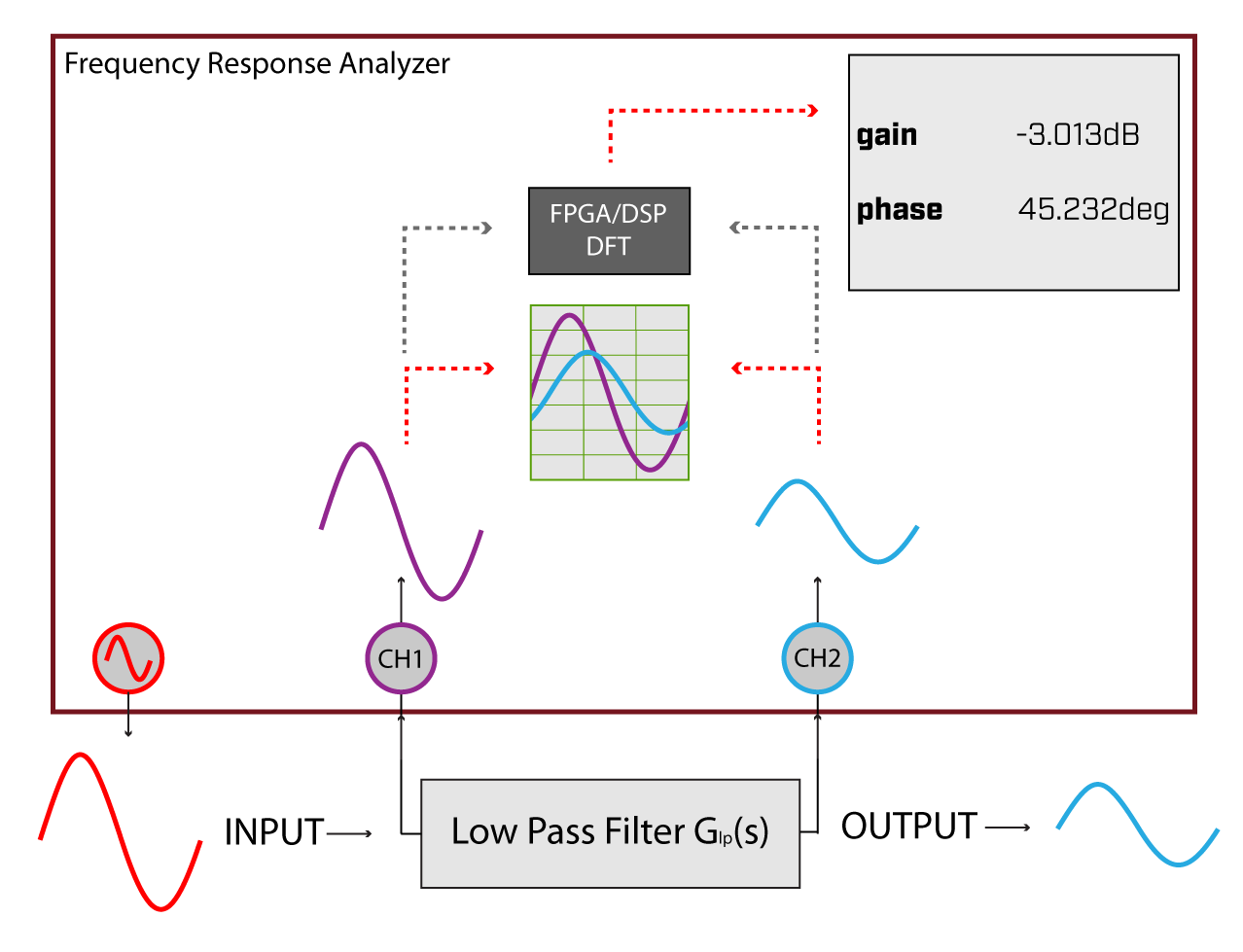
Once the test signals reach the inputs of the frequency response analyzer, they are signal conditioned with N4L proprietary ranging circuitry and then digitized via a high linearity ADC. After digitization, the data is passed to the FPGA/DSP for discrete fourier analysis. The DFT acts as a “notch filter” to extract only the injected signal frequency, all other frequencies are rejected. For example, if a 1kHz signal is injected into the circuit by the FRA generator, the frequency response analyzer utilizes the DFT process to extract the 1kHz component only from the signal passed to the FPGA.
Without the DFT process, the signal digitized by the frequency response analyzer would also contain noise. The DFT process provides excellent selectivity and very high (120dB) dynamic range.
The output of the DFT from both CH1 and CH2 are compared, with respect to both magnitude and phase shift. The absolute gain (CH2/CH1) is converted into a dB value and both dB gain and phase shift in degrees are displayed.