Power Supply Design and Test
Electronic power supplies generally fall into one of two categories; Linear or Switched mode, with the former utilising low frequency wound components and the latter, much higher frequency, and therefore smaller wound components. The size and efficiency advantages offered by switched mode designs comes at the expense of sometimes more complex control, greater electrical noise, and distortion.
It follows that measurement instrumentation used for the design and test of switched mode power supplies must be designed to manage practical challenges not easily overcome by conventional instrumentation.
Power consumption and non-linear loads
Power consumption and non-linear loads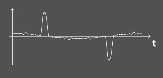
To a low voltage AC mains power source, an ideal load would behave as a pure resistance or simple impedance, with resistance and a first order reactance. In practice, most power supplies connected to an AC power represent a more complex load, particularly the increasingly common switched mode designs.
Load waveforms will be phase shifted, harmonically distorted or both.
Harmonic Analysis
Harmonic Analysis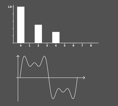
Impedance Measurement
Impedance Measurement
Losses and Efficiency
Losses and Efficiency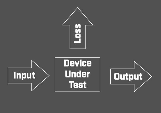
To fully understand losses and power supply efficiency, power measurements must include fundamental, harmonic, and wideband components.
Given knowledge of total power, fundamental and harmonics of the fundamental, noise and loss components can be derived
Inrush Test
Inrush Test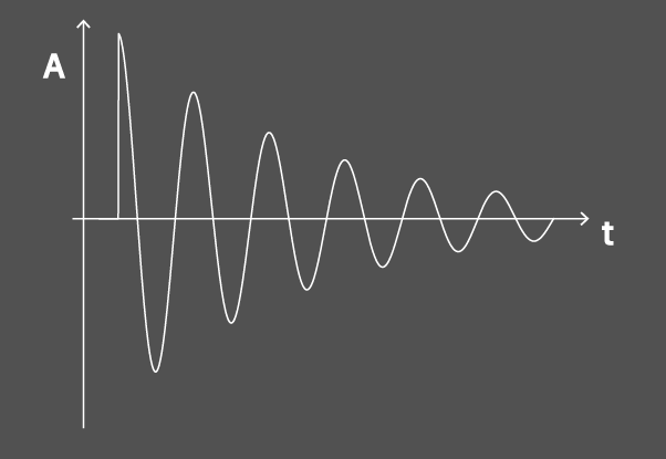
When first applying power to an electronic device, the associated circuitry will usually demand greater current than will be required in normal operation. This is commonly called the inrush current, and an understanding of maximum value is important for conductor rating, fuse selection and regulatory limits.
Since the inrush current associated with any load type will depend upon the point in a mains cycle at which power is applied, phase controlled inrush switching enables a user to quickly and reliably establish the maximum inrush value.